K4QKY "Don" is back on the air after having recently moved from The Crossings at Eastchase, an independent living community in Montgomery, Alabama where he and his wife, Pat, once resided. They are now once again enjoying the comforts of living in a real house which is also located in Montgomery.
Amateur Radio has always been his favorite hobby! He especially enjoyed the opportunity to build and preserve meaningful relationships with other hams all over the world. He became a licensed ham while in the Navy to facilitate telephone patch calls from aboard ships in the Pacific during his 28-year Navy career. He is especially grateful to all those hams who made those patches possible. He operated his own equipment including a Kenwood TS-520S, Yeasu FL-2100 linear amp, and a Cuscraft trap vertical antenna from five ships.
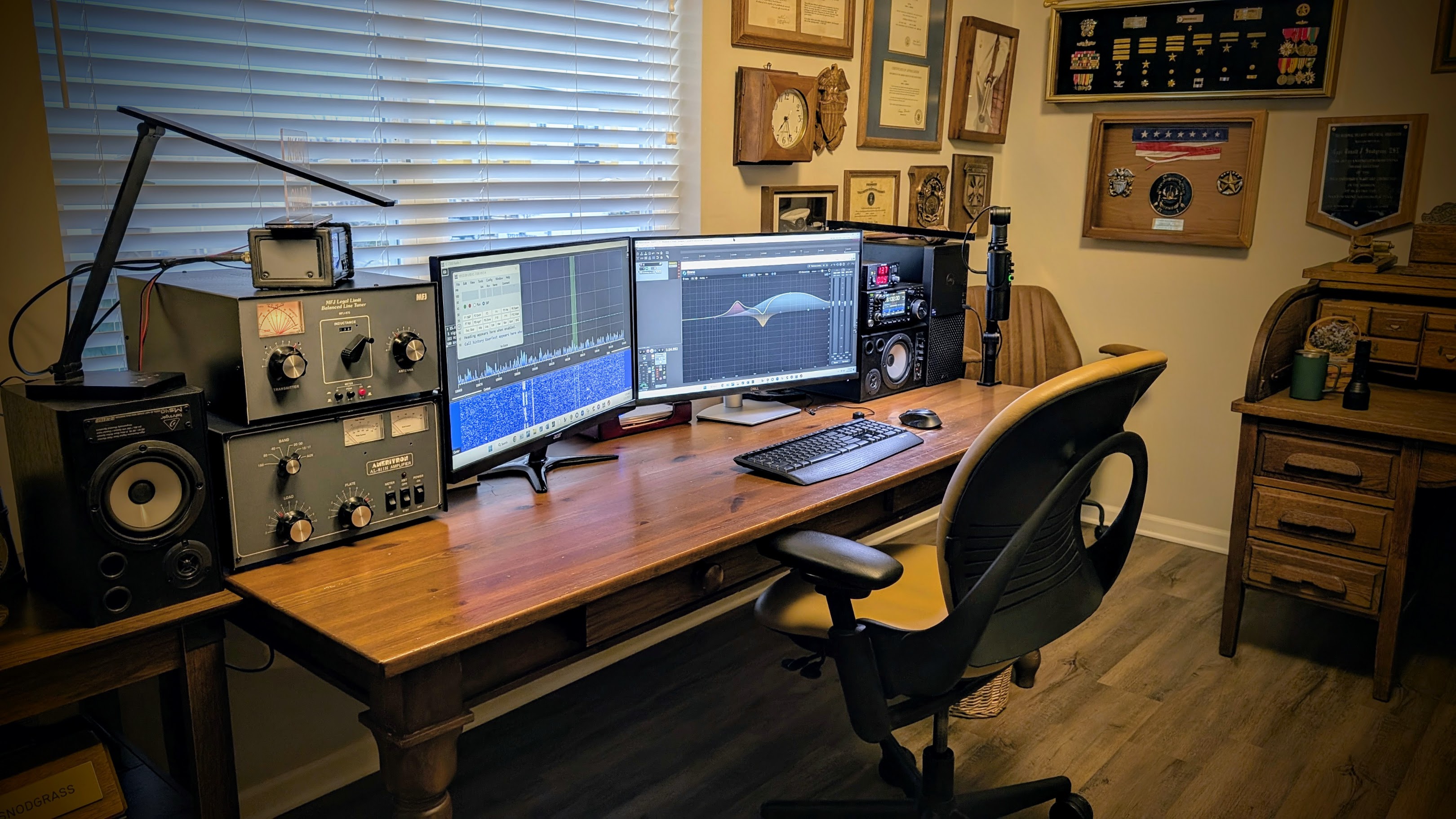
K4QKY's station components and equipment layout

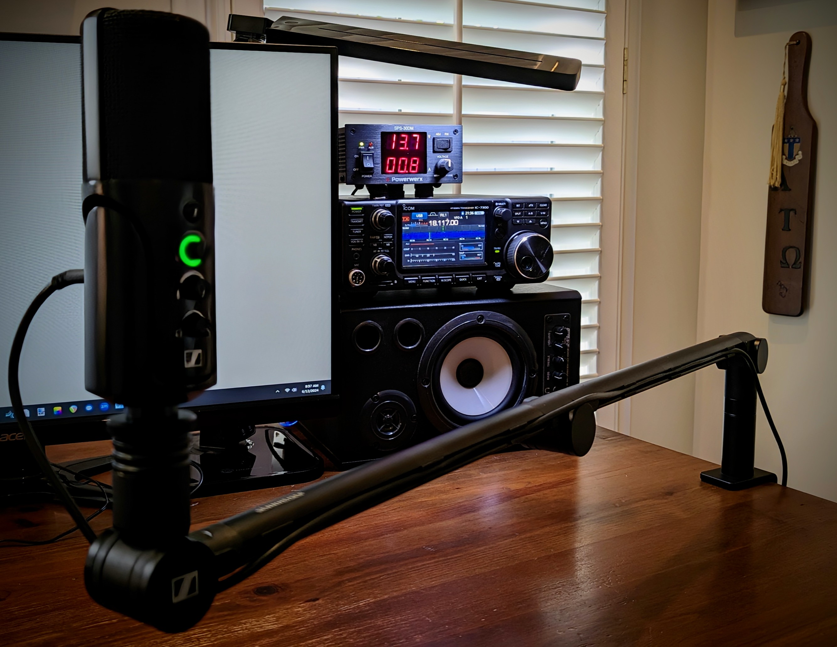
Icom IC-7300 transceiver together with Powerwerx SPS-30DM power supply, Behringer near-field digital monitors, and the Sennheiser Profile USB microphone with matching boom arm.

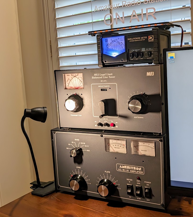
Ameritron AL-811H linear amplifier together with the MFJ-976 balanced line antenna tuner and a Daiwa CN-501H swr/power meter.
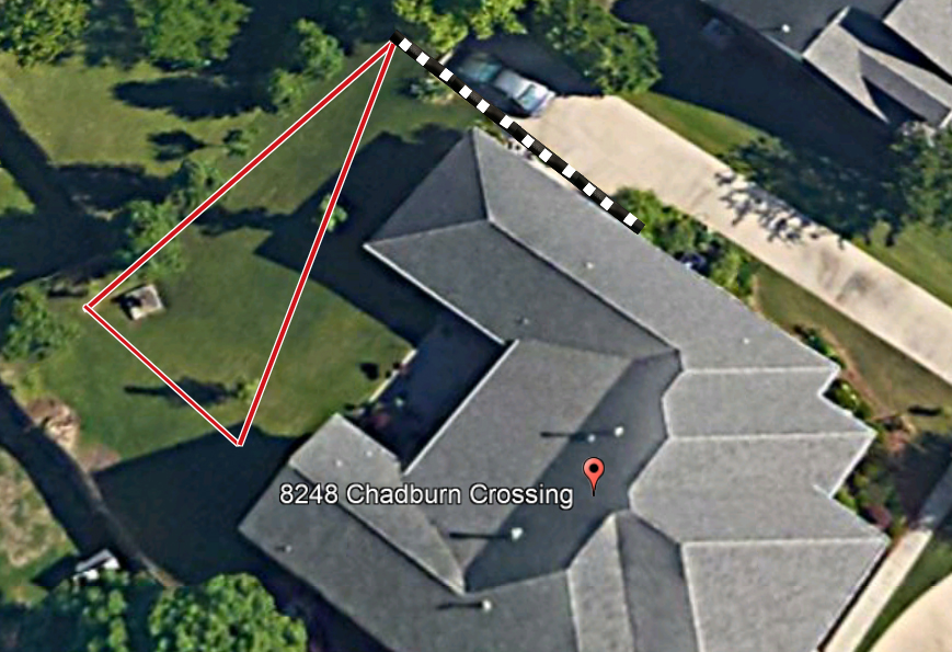
Delta loop antenna
The antenna system consists of an inexpensive and near invisible Delta thin wire loop wire antenna suspended from three points consisting two large trees, and the back corner of the the house as depicted in the photo above. Nylon halyards are used to isolate the antenna from the tree and the street light. Diagram A above depicts the overall layout of this loop cut to one full wavelength (272 ft) on the lowest operating frequency (80 meters). The mean height of the loop above ground is about 30 ft. Loop suspension attachment points consist of nylon pulleys attached to dacron halyards to maintain equal tension on all three sides of the loop.

The antenna is suspended about 350 ft above ground. No building alterations were necessary in order to route the 450 ohn tuned feed line from the equipment to the delta loop antenna as depicted in the above photograph. This delta loop wire antenna is fed with a 450 ohm ladder line running from a MFJ-976 balanced line antenna tuner in the ham shack.
Note: Hams employ various techniques for placing the loop suspension halyards like this over the tops of trees and othe structures. Many even "over-engineer" the process by adding spring tension devices, etc. K4QKY prefers to keep it simple by the use of 6lb colored (for best visibility) stranded fishing line, a hefty sinker, and a slingshot. Once the line has been launched over the tree, pull over a lightweight nylon cord. Finally, attach the cord to the halyard and pull it over the tree. Alternatively, adjust each halyard to achieve the desired tension in the loop.
Why feed a loop with a balanced feed line?
If you doubt the viability of feeding wire antennas like loops and dipoles with open wire line, read the following explanation courtesy of K5UA "Charles":
There are two kinds of line loss, the matched line loss, and the mismatch line loss. Matched line loss is measured at different frequencies in db per 100 feet when the line is terminated into a load that is identical to the characteristic impedance of the line. The loss increases as the frequency increases. Mismatched line loss is an additional attenuation of the signal because the line is terminated into a load that is different than the characteristic impedance of the line. This loss increases with frequency, but it also increases with the magnitude of the mismatch. Needless to say, lossy lines like the small coax have higher mismatched line loss numbers for the same amount of mismatch than the lower loss, large coax lines.
Matched line loss is unavoidable, but mismatched line loss is avoidable if the load can be matched to the line at the load end of the line. An example of this would be a gamma match at the yagi terminals to transform the 16-ohm impedance of the antenna to the 50-ohm characteristic impedance of the coax. Another example would be to use a 4:1 balun at the antenna terminals to bring the 16 ohms closer to 50 ohms.
The match can also occur at the transmitter end of the line, but the mismatched line loss would be there. The transmitter would be happy looking into a 50-ohm load, but the mismatched line loss would still be present because the load is not matched.
The beauty of an open-wire line is that the matched line loss is virtually zero. Even with large line/load mismatches, like 10:1 or 15:1, the additional mismatched line loss is very low. As long as the user has a conjugate match on the transmitter end of the line using an antenna-matching network, virtually ALL power is radiated by the antenna. Power can not disappear, it is either radiated or lost in the line by attenuation of the dielectric material between the transmission line wires. This is why a random wire of reasonable length may radiate MORE power when fed
by open-wire line through a tuner, then a perfectly matched half-wave dipole fed with small coax, assuming the feed line length of each is over 100 feet.
The net effect of this is that you can put up a random length dipole (or a loop as discussed here) and use it on all bands with very little line loss and not have to worry about a bunch of resonant dipoles interfering with each other.
K5UA, in another email, goes on to say:
The probability that any single-element antenna is going to have a feed point impedance of 50 +/- j0 ohms is virtually ZERO.
Likewise, when I hear of someone bragging about their quad or yagi that is 50 ohms at resonance, I always ask them how much gain and front to back they have to sacrifice to get that 50-ohm feed point impedance. When God was designing the universe and the laws of physics, he did not realize that the tail (50-ohm coax) was going to wag the dog (gain/front-to-back/multi-band operation) in the antenna world.
The concept of resonance also appears to baffle most amateurs because they do not know or understand the three components of impedance (resistance, inductive reactance, and capacitive reactance). A lot of amateurs believe that resonance occurs only when the antenna impedance has the same 50-ohm resistive component as the coax impedance. Actually, resonance is simply defined as the absence of the reactive component of impedance, or in other words, a purely resistive load. If the impedance of a resonant dipole is 80 ohms and you're using a 50-ohm coax, the best SWR you can achieve is 1.6 to 1.
SWR messes with the ham mind, especially with beam antennas where the SWR curve is hardly ever centered on the resonant frequency of the antenna because the feed point impedance at resonance is rarely 50 ohms. The SWR curve is, therefore, skewed to one side or the other of resonance and non-symmetrical. The worse the mismatch of the coax and the antenna at resonance, the greater the skewing effect and asymmetry of the
SWR curve.
Note: K4QKY has typically used ladder line-fed full-wave loops at previous QTHs. He has also experimented with a two-element Delta loop array antenna fed with a 300-ohm ladder line. More about the design and construction of this array at https://donandpat.com/files/parasitic delta loop array.pdf.
Click http://donandpat.com/amateur-radio/audio-processing to learn how K4QKY uses digital audio processing techniques. Email
